For all models listed here the analysis method will be direct Finite Element Analysis using a dedicated analysis machine. This may be installed on the user's own PC (separate to SonoAnalyzer) or on a remote cloud server. The latest models in SonoAnalyzer version 2 require a version 2 analysis server.
User-geometry models (Pro FEA - version 2 only)
 Available from version 2 onwards, this new model type allows users to supply their own geometry as a solid model in STEP format. In princilple this make it possible to analyze any geometry; in practice there are practical limits, as well as issues to consider which don't apply to any previous models. A brief summary follows, with a more detailed discussion to be created.
The analysis process for these models is more involved than before:
Solid geometry is imported in STEP format (available from most / all CAD packages). From this, a mesh of tetrahedra (4-noded, ie. corners only) is generated automatically by Netgen with parameters set by the user selecting a particular Mesh size on the Analysis tab. This is converted to a mesh with midside nodes (10-noded tetrahedra) by CalculiX cgx. This is important for the finite-element analysis; midside-node elements perform much better than elements with corner nodes alone. Then the positions of the midside nodes are adjusted by SonoAnalyzer to follow as closely as possible the curved surfaces in the original geometry.
FEA is run using CalculiX ccx as for previous models, and then SonoAnalyzer reads the results for display. In SonoAnalyzer version 2 all common stress and displacement contour plots are available from within the program itself but the CalculiX postprocessor cgx can also be used to visualize results, as before.
Limitations:
One important limitation of this model is that currently, within a single analysis, only one geometry file can be imported and only one material can be selected. It may be possible to remove this limitation in a future version but there are significant hurdles to overcome.
Fine detail can cause problems. Netgen's meshing algorithms adjust mesh size automatically, fitting a fine mesh to locations on the sonotrode with fine detail and a coarser mesh elsewhere. However this is not aways desirable. In sonotrode design there is often fine detailing on the output surface to match the component being welded, but this is a region of low stress where a fine mesh is not needed in order to achieve an accurate prediction of the resonant frequency and mode shape. So in some cases user intervention may be required to simplify the geometry. The selection of meshing parameters is also important and not necessarily intuitive. These issues will be discussed in detail on a new page to be created.
Multi-component stacks (Pro FEA)
Any of the following four cylindrical-profile #4 models can be combined to form a stack of several components. Different materials may be chosen for each component in a stack, and for each core material.
 This might be useful in several different cases:
- Transducer design. While the piezo-electric properties are not considered in this purely elastic analysis, results so far seem reasonably accurate.
- Stacks of components, eg. booster, sonotrode to discover any unusual issues with the combination (normally, each component is tuned separately to the same working frequency and this works well)
- Composite sonotrodes with a tip made from a different material
- Complex shapes where more than 12 sections (as available in the user-defined shapes) are needed to accurately represent the shape.
Dimensional ranges / limitations:
Each component is subject to the same dimensional ranges as above but there is no fixed limit on the number of components that can be analyzed together. Practically the limit on model complexity will be determined by the capability of the analysis server and the PC running SonoAnalyzer. Stacks of 4 components at standard mesh size can be analyzed.
#4 Pro models
New #4 analysis types are available for SonoAnalyzer Pro from version 1.7.0, replacing the earlier #3 models which are now deprecated. The external profiles are unchanged: stepped / conical / exponential / user-defined. The internal hole options are also unchanged: solid, simple or with a user-defined profile. New in the #4 models is an optional "core" component of a simple cylindrical shape or profiled like the hole, which can be used to model a central screw inside a sonotrode. In combination with the option to stack multiple components together this makes it possible for the first time to model a sonotrode with a hard tip attached by a screw or a sandwich-construction ultrasonic transducer.
For the simple cylindrical hole and core, the core diameter must be less than or equal to the hole diameter. Using the profiled hole and core, the same set of lengths is used for both and within each section the core diameter must be less than or equal to the hole diameter. Where the core and hole are of equal diameters they will be modelled as if perfectly joined together. If the core is smaller in diameter than the hole it will be free to vibrate separately. Likewise if the core and hole both feature a step in their profiles at the same point, the matching surfaces will be joined together for the purpose of the finite element model. If there are no regions of contact the core will be free to vibrate independently of the rest of the sonotrode and the results will include vibration modes for each separately.
Limitations:
The length of the core component must be less than or equal to that of the surrounding sonotrode. If the core is required to extend further then additional elements may be added.
The perfect join offers a good approximation to a threaded connection between screw and threaded hole, but doesn't exactly represent the way that stresses are distributed through the threads. Users are recommended to use caution with the results until proven with real results.
Matching surfaces which are not exactly parallel or perpendicular to the axis of the sontrode (ie. conical surfaces) will not be joined correctly. This limitation may be addressed in a future update.
Pre-stress modelling (eg. tension in the screw with corresponding compression in the sonotrode) is not currently available. The user is responsible for ensuring that the tension in the screw is sufficient to maintain compression across any joins. If this is not done correctly the sonotrode / transducer may exhibit extreme "chatter" as the mating surfaces separate under the alternating stresses; in this case the resonant frequencies may also differ considerably from the model predictions.
Linked piezoelectric - mechanical analysis is not available; the finite-element analysis is based on simple elastic material properties.
 User-defined Sonotrode #4 (Pro FEA)
The outside profile definition is similar to the #3 model described below - an arbitrary user-defined profile defined by a series of diameters and lengths. Blend (fillet) radii may also be included to smooth the transition between sections, including the final (output) section, allowing a radiused or even fully-spherical tip profile. An internal profile is also possible, defined in a similar way. For less complex requirements a simple through hole may be specified at a fixed diameter, or the interior may be set as solid.
A simple cylindrical or profiled internal "core" may also be defined using the same lengths but a different set of diameters. In the FE model, core and sonotrode will be joined together in regions where the hole and core diameters are equal, or where both profiles have a step (zero length) and the diameters overlap.
Dimensional ranges:
For each individual external section:
Length 0 to 150mm
Diameter 2.5 to 150mm
For each individual internal section:
Length 0 to 150mm
Diameter 0 to external diameter at that location
Blend radii (two external and two internal per model) 0 to 1000mm, subject to the blend fitting within the section lengths each side
Overall length 10 to 750mm (may be extended using multiple components)
Core profile is subject to the same limitations as the internal profile, and its diameter must be less than or equal to the surrounding hole.
This model has been designed to offer maximum flexibility to the expert user. However this also makes it possible for the user to specify impossible shapes, eg. internal diameter larger than external at some point. While the program will attempt to catch these problems and flag them, it's ultimately up to the user to view the shape on the 3D display and identify issues. The sectional view (selected automatically while defining hole properties) is very useful for this.
 Stepped Sonotrode #4 (Pro FEA)
The outside profile definition is similar to the #3 model described below - comprising two solid-cylindrical volumes (corresponding to the input and output of the sonotrode) joined by a radiused step. Top and overall lengths are defined independently, or the top length can be set as a percentage of the total. The blend radius used for stress-relief on the internal corner is user-defined and may be larger than the step. An internal profile is also possible, or for less complex requirements a simple through hole may be specified at a fixed diameter (as shown), or the interior may be set as solid.
A simple cylindrical or profiled internal "core" may also be defined using the same lengths but a different set of diameters. In the FE model, core and sonotrode will be joined together in regions where the hole and core diameters are equal, or where both profiles have a step (zero length) and the diameters overlap.
Dimensional ranges:
Overall length from 2.5 to 300mm (may be extended using multiple components)
Top length from 1.25 to 200mm, subject to overall length
Input and output diameters 1 to 150mm
Blend radius 0 to 1000mm, subject to the blend fitting within the profile length
Internal section (simple hole or profiled) to be always within bounds of external shape
Core profile is subject to the same limitations as the internal profile, and its diameter must be less than or equal to the surrounding hole.
 Exponential Sonotrode #4 (Pro FEA)
The outside profile definition is similar to the #3 model described below - comprising two solid-cylindrical volumes joined by an exponential curve. Input, output and overall lengths are defined independently, or the top length can be set as a percentage of the total. An internal profile is also possible, including blind hole(s) (as shown) or for less complex requirements a simple through hole may be specified at a fixed diameter or the interior may be set as solid.
A simple cylindrical or profiled internal "core" may also be defined using the same lengths but a different set of diameters. In the FE model, core and sonotrode will be joined together in regions where the hole and core diameters are equal, or where both profiles have a step (zero length) and the diameters overlap.
Dimensional ranges:
Overall length from 2.5 to 300mm (may be extended using multiple components)
Input length from 0 to 200mm, subject to overall length
Output length from 0 to 200mm, subject to overall length
Input and output diameters 1 to 150mm
Internal section (simple hole or profiled) to be always within bounds of external shape
Core profile is subject to the same limitations as the internal profile, and its diameter must be less than or equal to the surrounding hole.
 Conical Sonotrode #4 (Pro FEA)
The outside profile definition is similar to the #3 model described below - comprising two solid-cylindrical volumes joined by a frusto-conical section. A new feature in this version is that a blend radius may also be defined on the internal corner, similar to the stepped designs. Input, output and overall lengths are defined independently, or the top length can be set as a percentage of the total. An internal profile is also possible, including blind holes or varying diameters (as shown) or for less complex requirements a simple through hole may be specified at a fixed diameter or the interior may be set as solid.
A simple cylindrical or profiled internal "core" may also be defined using the same lengths but a different set of diameters. In the FE model, core and sonotrode will be joined together in regions where the hole and core diameters are equal, or where both profiles have a step (zero length) and the diameters overlap.
Dimensional ranges:
Overall length from 2.5 to 300mm (may be extended using multiple components)
Input length from 0 to 200mm, subject to overall length
Output length from 0 to 200mm, subject to overall length
Input and output diameters 1 to 150mm
Blend radius 0 to 1000mm, subject to the blend fitting within the profile length
Internal section (simple hole or profiled) to be always within bounds of external shape
Core profile is subject to the same limitations as the internal profile, and its diameter must be less than or equal to the surrounding hole.
#3 Pro models
#3 analysis types have been available since SonoAnalyzer Pro beta / release-candidate from version 1.5.0. The cylindrical types were deprecated in favour of the #4 models above, but the rectangular block models are still current.
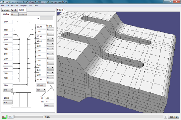 Slotted Rectangular Block Sonotrode #3 with User-defined profile (Pro FEA)
Also using a similar external profile generator, the Pro version of the rectangular block sonotrode also allows for lengthwise slots with semi-cylindrical ends.
Dimensional ranges:
For each individual external section:
Length 0 to 150mm
Thickness 2.5 to 150mm
Blend radii (two per model) 0 to 1000mm, subject to the blend fitting within the section lengths each side
Overall length 10 to 750mm
Overall width 10 to 500mm
Up to 9 slots (all identical):
Width 1 to 25mm
Distance from ends 5 to 95mm, subject to profile shape
Distance between slots 5 to 80mm
Distance from edge of sonotrode to edge of slot 5 to 250mm
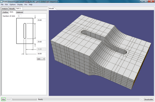 Slotted Stepped Rectangular Block Sonotrode #3 (Pro FEA)
The rectangular block equivalent to the stepped sonotrode above plus a number of lengthwise slots with semi-cylindrical ends.
Dimensional ranges:
Overall length from 10 to 750mm
Top length from 5 to 500mm, subject to overall length
Input and output thicknesses 2.5 to 150mm
Width 10 to 500mm
Blend radius 0 to 1000mm, subject to the blend fitting within the profile length
Up to 9 slots (all identical):
Width 1 to 25mm
Distance from ends 5 to 95mm, subject to profile shape
Distance between slots 5 to 80mm
Distance from edge of sonotrode to edge of slot 5 to 250mm