In the previous article we saw how to adjust the dimensions of SonoAnalyzer models using setup variables. But if we are analyzing geometry in a STEP file, all the dimensions are "baked in" during the CAD design phase. SonoAnalyzer has no way to adjust them... or does it? Here are three possible methods:
1. Trim
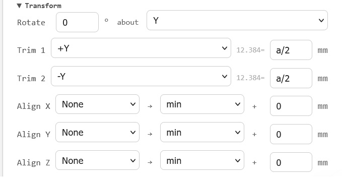 The simplest way to modify a STEP file is using the trim function to remove material from one or both ends. Open the "Transform" panel, under "Trim 1" select +Y and enter a value, eg. 5mm. This will trim 5mm off the input side of the sonotrode. Use -Y to trim from the output side. Both can be used together by entering values for both "Trim 1" and "Trim2". And again, the numeric value for the amount of trim can also be replaced by one of the analysis variables. In this case we might use "a/2", since we're trimming the same amount off both ends - then the value of a will be the reduction in length. So we can reproduce the simple stepped sonotrode tuning described previously using a STEP file and by trimming the same amount from both ends we ensure that no matter what trim is applied the step remains in the middle of the length.
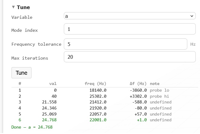 A new example file is now available to demonstrate this - see Examples -> Trim -> Base_step_trim. The tuning process requires at least a Base subscription as the Free trial does not include STEP file analysis. The STEP file in this case is based on the 140mm maximum length of the earlier tuning example with values of a ranging from 0 to 40mm, so that the length range, and hence the frequency range, should be identical to the previous analysis. And indeed, when tuning to 22kHz is done the tuned value of a is 24.77mm (giving a length of 115.23mm) and the achievable frequency range is from 18.2kHz to 25.3kHz.
From version 3.006, this tuning analysis can be found in Examples -> tune -> base step trim.
Trim also works on the X and Z axes if required - adjusting the width and depth of block sonotrodes - as well as inside and outside diameters, which can be used to modify step-up ratios or tune radial-mode resonators. But what if your STEP file includes geometry featuring a curved or complex profile at the end you want to tune? In that case another approach must be used.
2. Split and recombine
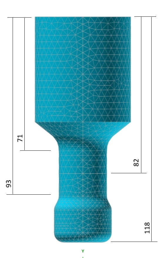 If the simple trim method is not appropriate, look for an unchanging section within the design that could be adjusted to tune the sonotrode. Most designs include at least one region that is prismatic (typically cylindrical) where length could be conveniently added or subtracted. As an example, this is the old standard SonoAnalyzer profiled sonotrode exported as a STEP file. The overall length is 118mm and the cylindrical region on the output side extends from 70 to 93.8mm. Rounding down we might use the region from 71mm to 93mm for tuning, a total of 22mm. The middle of the tuning region is therefore 82mm from the top (input) end and 36mm from the bottom (output) end.
To set this up we can first trim on +Y, removing the input surface and everything below it down to the middle of the cylindrical tuning region at 82mm, leaving the lower half of the tuning region and down to the output. Then add a second geometry tab duplicating the first ("+" -> "Duplicate tab") and on the second tab trim on -Y to 36mm - this removes the output end of the sonotrode and the lower half of the tuning region. Now with the two geometry components defined and default stacking, the result is a combined sonotrode with the exact same length (118mm) and geometry as the original. Re-running the FEA calculation for the new geometry will confirm this.
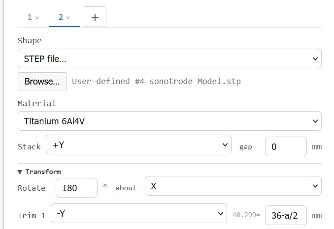
But where the old geometry had fixed dimensions, here we can change the amount to trim from each part - increasing or reducing the overall length by up to 22mm. To handle this conveniently we will use the variable "a", as follows: In the first geometry tab, change the value 82 to "82-a/2". In the second change 36 to "36-a/2". Using a/2 in both means that when summed, the change in overall length is equal to the value of "a", and the negative sign ensures that a positive value of "a" corresponds to an increase in length. Given the constraints of the original geometry the range of valid values for "a" is from -22 to +22mm.
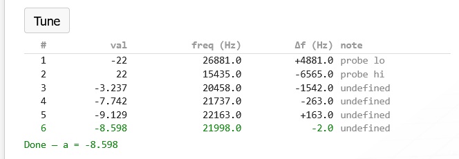
And this is the progress of tuning to 22 kHz. The tuned length is 118 - 8.6 = 109.4mm.
From version 3.006, this tuning analysis can be found in Examples -> tune -> base step split recombine.
Why not stack with a negative gap instead? Indeed the gap between components can be set negative to define an overlap but generally this technique is recommended only for components that fit into one another, like a screw in a hole. Overlapping physical geometry is handled by gmsh with boolean operations but depending on the exact dimensions this can lead to degenerate geometry fragments being left behind, causing the meshing to fail. So using a negative gap for this purpose may work initially but fail unexpectedly for specific values of overlap.
3. Split, patch and recombine
A tweak to the method above may be more appropriate for geometry where the tunable section is very short. In this case we split the original geometry to the minimum possible lengths so the first part comprises the input and extends only to the beginning of the tunable region, while the second part extends from the end of the tunable region to the output. So the tunable region itself is removed and replaced ("patched") with new geometry. This could be a simple shape (cylinder or block) or for more complex prismatic geometry another STEP file trimmed to length using the trim function. The three components are then stacked with zero gaps as before and tuning works by changing the length of the patch section. Of course this only helps if the frequency needs to be tuned down - to increase the frequency beyond what can be achieved by reducing the tuning length to zero requires finding another way to change the geometry.